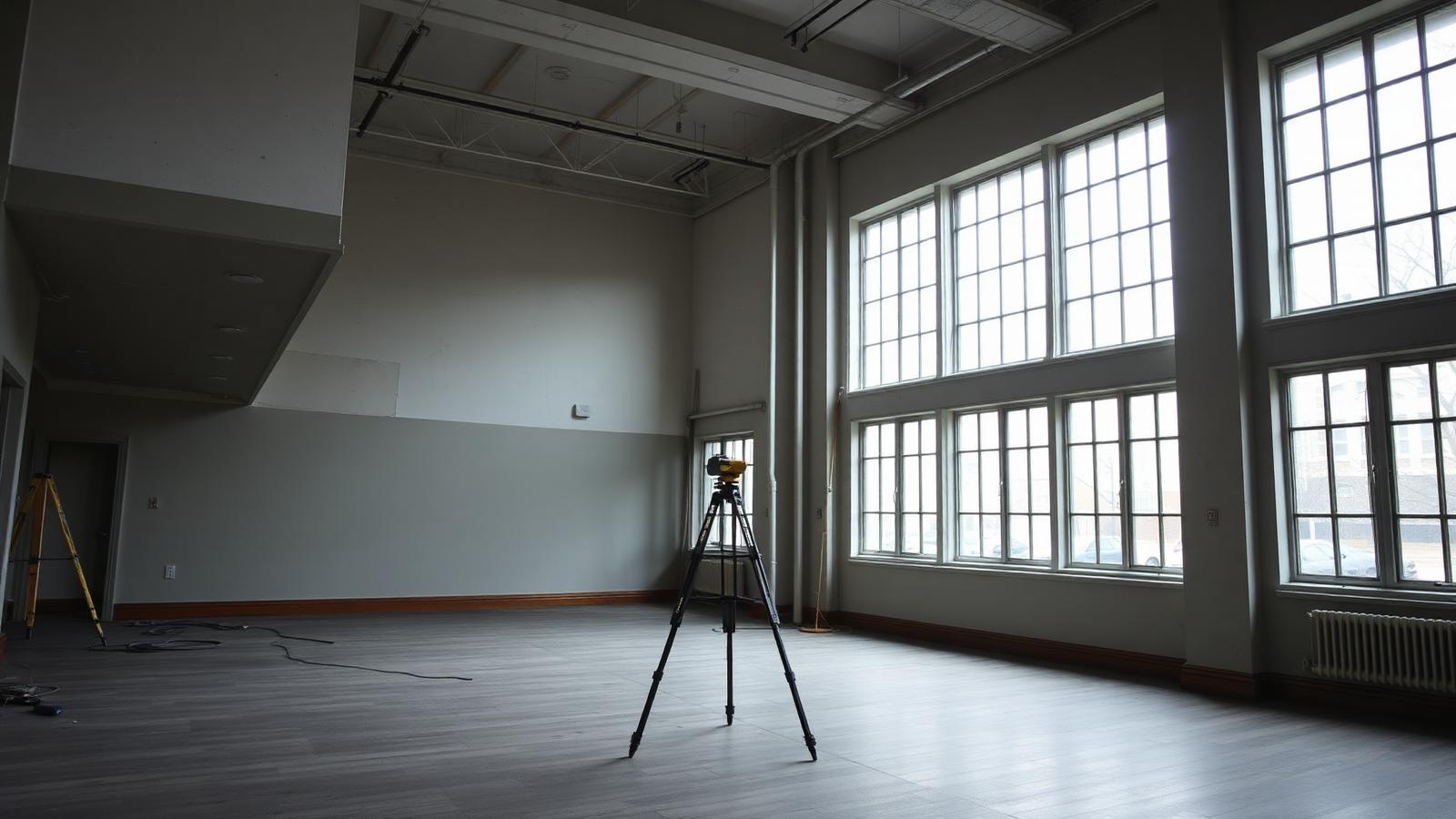
TL;DR
Scan-based floor plans hold ±6 mm registered accuracy against ±1/2 inch for careful tape work, take one field day per 100,000 sq ft instead of 3–5, and deliver in 3–7 business days. On one 68,400 sq ft Columbus TI, the scan caught a stair 2.25 inches off the plan grid and a hidden 10.5-inch beam drop.
Floor plans that stand up to demolition day
Renovations don’t fail because of bold design ideas. They fail because the first sketch started on the wrong geometry. One mislocated chase. A corridor that’s 2 inches shy of clearance. A stair that doesn’t land where the old drawing said it would. That’s when the RFIs start stacking up and your schedule bleeds.
Accurate as-built floor plans aren’t a nice-to-have for renovation and adaptive reuse. They’re the control baseline for every dimension you draw after that. We build them from reality, not from hopes.
“If you can’t trust your floor plan, you can’t trust your takeoffs, your coordination, or your permit set. Get the geometry right, and the rest of the project stops fighting you.”
What usually goes wrong with field-measured plans?
Even careful hand measurement misses important conditions in existing buildings. Here’s what we see most when we’re called in to rescue a project:
- Parallel walls that aren’t actually parallel (off by 1–2° over 80–100 ft)
- Shafts and risers that drift floor-to-floor (1–3 in. stack offsets)
- Drop ceilings hiding beams, soffits, VAV boxes, or transfer ducts
- Legacy MEP penetrations that steal corridor width
- Inconsistent wall thicknesses in masonry and plaster renovations
- Stair runs with inconsistent riser heights and landings that don’t square to grids
- Skewed cores in prewar structures where nothing is orthogonal
Each of those can sink a layout if you discovered it after demolition, not before.
How do we produce reliable plans with 3D scanning?
We capture reality at walking pace with the NavVis VLX3 mobile LiDAR and fill in complex or shiny spaces with terrestrial scanners (Leica RTC360, FARO Focus). The result: a clean, registered point cloud with true building geometry that drafts into floor plans you can trust.
- Capture throughput: 80,000–120,000 sq ft per day with VLX3 SLAM; 1–2 days for typical 100k sq ft buildings
- Accuracy: ±6 mm registered to control; typical point spacing 5–10 mm at 10 m
- Deliverables: DWG and PDF floor plans; optional Revit LOD 200–300; pano walkthroughs for remote verification
- File formats: E57 master (20–80 GB typical per 100k sq ft), RCP/RCS for Autodesk, LAS on request
- Registration: cloud-to-cloud with control targets; survey tie-in to a single coordinate system; QA variance report for every level
We don’t skip control. On multi-floor jobs, we set checkerboard or sphere targets and run a short traverse to lock each level to the same coordinate system. Mechanical mezzanines, crowded boiler rooms, and glassy lobbies get a quick RTC360 loop for clean geometry where SLAM alone struggles. Then we QC the registration with cross-sections at columns, cores, and known dimensions.
Numbers you can design to
- Plan dimensions trace directly to point cloud geometry; we draft to wall faces, not averages
- 360° imagery every 3–5 m helps verify valves, panels, and door swings without a second site visit
- Turnaround: 3–7 business days for 2D floor plans on projects up to 100k sq ft; larger campuses schedule in phases
Traditional measurements vs. scan-based floor plans
| Item | Tape/Handheld Laser Field Measure | Scan-Based Floor Plans (ZEALOT) |
|---|---|---|
| Coverage | Spot checks and linears | Full-fidelity geometry wall-to-wall |
| Accuracy | ±1/2 in. if clean; worse in clutter | ±6 mm registered across each floor |
| Time on site | 3–5 days per 100k sq ft | 1 day per 100k sq ft (VLX3) |
| Site revisits | Common for missed areas | Rare; 360° pano audit fills gaps |
| Documentation | Sketches and photos | Point cloud (RCP/E57) + pano tour |
| Rework risk | High in complex areas | Low; variances flagged early |
| Cost of missed condition | Change orders and delays | Caught predesign; mitigated in layout |
What’s included in a scan-based floor plan?
Our standard as-built floor plans are drafted in AutoCAD to your layer standards (AIA NCS by default) and include:
- Exterior and interior walls with thickness and material tags when visible
- Doors, windows, sidelights, and openings with widths, heights, and swings
- Structural columns, shear walls, cores, and load-bearing elements
- Stairs, elevators, and shafts with centerlines and rough openings
- Casework, built-in millwork, and fixed plumbing fixtures
- Major mechanical equipment footprints and access clearances where feasible
- Room names, numbers, and dimension strings to key datums
- Overall building dimensions, level elevations, and a shared coordinate
Add-ons drafted from the same point cloud—no second mobilization:
- Reflected ceiling plans with soffits, beams, sprinklers, major diffusers
- Building sections and select elevations
- Exterior façade control lines for storefront and curtainwall
See our service pages for details: 2D/3D Floor Plans and Scan to CAD. If your team prefers to model, we also deliver Scan to BIM in Revit at LOD 200/300/400 with documented assumptions.
Field notes from Columbus: 68,400 sq ft, one mobilization
A design-build team in Columbus asked us to clean up a fast-track office TI across four floors (68,400 sq ft). The landlord had a PDF plan from 2009. Elevators, shafts, and several demising walls had moved—nobody had an accurate current plan.
- Capture: 6.5 hours on site with the NavVis VLX3; two short RTC360 loops in a glassy lobby and a data center
- Registration: control targets on each floor, variance under 4 mm at core columns
- Deliverables: DWG/PDF floor plans, RCP with aligned pano viewer, one building section through the core
- Turnaround: 4 business days
What the scan found:
- The central stair landed 2.25 in. east of the plan grid; corridor width at Level 4 would have violated egress if built per old drawings
- A pair of wet stacks drifted 1.75 in. between Level 2 and Level 3, affecting restroom chase alignments
- A soffit above the existing reception hid a beam drop of 10.5 in. across 24 ft—missed in every site walk
The design team corrected their layout before demo. The PM tracked 9 RFIs avoided and estimated $26,800 in potential rework prevented. No extra site visits were needed; 360° imagery covered every decision.
For a larger example, see how we documented 180,000 sq ft in three weeks in our Downtown Mansfield case study.
Where do accurate plans matter most?
- Adaptive reuse and historic conversions
- Prewar and industrial buildings rarely follow modern grids. Our scans capture those irregularities so your unit plans and MEP routes respect reality. For preservation work, scanning supports—never replaces—measured drawings, archival research, and on-site investigation. See our work in adaptive reuse and how 3D scanning supports historic documentation.
- Tenant improvement and office fit-outs
- Lease exhibits, demising layouts, test fits, and permit sets move faster when the floor plan is right the first time. Architects use our pano-linked plans to cut field visits; here’s how they eliminate site trips.
- Renovation permitting
- Jurisdictions want existing-conditions drawings that match reality. Our stamped as-builts slot neatly into submittals and keep reviewers focused on design, not guesswork.
- Facility management
- Owners use scan-based plans for space allocation, life-safety updates, and capital planning. A one-time capture becomes a permanent baseline.
We serve architecture, construction, and engineering teams across Ohio and nationwide.
From floor plans today to BIM tomorrow
Start with 2D floor plans to get your layout moving. When it’s time to coordinate, the same point cloud upgrades to a Revit model at LOD 200 or 300 without a second capture. We align our modeling to your BIM Execution Plan and document every assumption. Not sure what to specify? Use our templates: Scope of Work for Scan to BIM and LOD 200 vs 300 vs 400.
As projects evolve, we can add ceilings, structure, and MEP rough-ins while keeping the model light enough for design. For as-built record sets or turnover, see our As-Built Documentation.
Practical delivery details that save you time
- Coordinate system: We establish a shared project base point and elevation; we can tie into survey control if provided
- CAD standards: AIA NCS layers by default; we map to your layer and block libraries if you share them
- QA: We provide a variance report and annotated screenshots of any irregular geometry worth discussing
- Files you receive:
- DWG + PDF floor plans per level
- RCP project and E57 master exports
- Pano viewer with level bookmarks for remote walkthroughs
- Typical sizes: 100k sq ft produces 35–70 GB of scan data and 10–20 MB per floor in DWG/PDF
- Turnaround: 3–7 business days for up to 100k sq ft; larger sites scheduled in rolling packages so design doesn’t wait
If you’re scheduling a scan, a quick site prep checklist—clear access, lights on, doors unlocked—can save hours. Share this with your client: How to Prepare Your Site for a 3D Laser Scan.
Ohio-based, built for speed, ready to travel
We’re local to Ohio—Cleveland, Columbus, Cincinnati, Mansfield—and mobilize nationwide. On tight interiors, the NavVis VLX3 gets us through entire floors before lunch. Where reflectivity or tight machinery would stump SLAM, the RTC360 or FARO Focus fills the gap. The output is consistent, accurate, and draftable.
Curious about the hardware behind the workflow? See how we capture at walking pace in Inside the NavVis VLX3 or review our stack on the technology page.
When your renovation starts on real geometry, you stop paying for surprises later. That’s the point.