TL;DR
The NavVis VLX3 captures buildings at walking pace — 25,000–40,000 sq ft per hour in open offices — while SLAM fuses LiDAR, IMU, and camera data into a cloud that registers to ±6 mm against control. The discipline is in the method: steady 0.8–1.2 m/s pace, frequent loop closures, and targets at transitions.
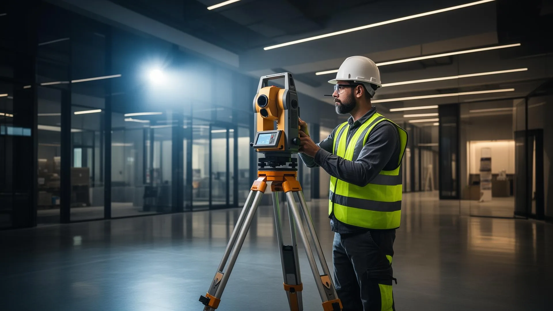
Renovations and retrofits move faster when the existing conditions are documented without guesswork. That’s why we carry the NavVis VLX3 into plants, hospitals, and warehouses across Ohio and beyond. It lets us capture large interiors at walking pace and still deliver millimeter-grade data your design team can trust.
What’s actually inside the VLX3?
The VLX3 is a wearable mobile LiDAR system. You strap it on, walk, and it maps in real time. Under the hood:
- Two multi‑layer LiDAR sensors with overlapping fields of view for dense coverage in tight corridors and large volumes.
- 360° HDR cameras to colorize the point cloud and document finishes, labels, and equipment tags for coordination.
- A tightly coupled IMU and visual-inertial odometry pipeline that feeds the SLAM engine six degrees of motion.
- Onboard processing for quick field QA, plus project‑level registration in the post‑processing suite.
For AEC work, that translates to point spacing of roughly 5–10 mm at 10 m stand-off, with registered accuracy typically ±6 mm to survey control when the route includes strong loop closures and well-distributed targets.
How does SLAM hold accuracy at walking pace?
Tripod scanners (Leica RTC360, Faro Focus) establish accuracy scan-by-scan from fixed stations. Mobile LiDAR leans on SLAM: it fuses LiDAR geometry, IMU motion, and camera tracking continuously. The catch is drift. The cure is good practice.
Here’s how we keep numbers tight:
- Plan routes that naturally loop back on themselves.
- Place surveyed control targets and unique AprilTags at choke points, long corridors, and stair cores.
- Keep walking speed steady (0.8–1.2 m/s) and avoid abrupt pivots that can induce motion blur in feature‑sparse areas.
- Revisit key rooms from multiple directions to give the algorithm redundant geometry.
We still do proper survey. SLAM gives the shape; control fixes it to the project coordinate system. On multi-floor work, we tie each level with vertical control to stop “floor drift.”
“The trick isn’t walking fast. It’s walking smart—closing loops, touching control, and giving SLAM the geometry it needs so the modeler isn’t chasing ghosts later.”
When does mobile LiDAR beat tripod scanning — and when doesn’t it?
Tripods still matter. But in most occupied buildings and large interiors, walking‑pace capture wins on safety, schedule, and cost.
| Scenario | NavVis VLX3 (mobile) | RTC360 / Focus (tripod) |
|---|---|---|
| Throughput in open office | 25,000–40,000 sq ft/hour | 3,000–6,000 sq ft/hour |
| Throughput in MEP-dense plant | 12,000–18,000 sq ft/hour | 1,500–3,000 sq ft/hour |
| Typical registered accuracy to control | ±6 mm | ±4–6 mm |
| Image capture | Continuous 360° | Station-based HDR |
| Best use cases | Large interiors, long corridors, multi-level routes, occupied spaces | Facade elevations, small rooms needing ultra-high static detail, exterior topo tie-in |
| Downtime impact | Minimal—keep walking around occupants | Higher—set up, move tripod, keep clear line-of-sight |
We often pair methods. For example, mobile for the bulk of a hospital wing and tripod sets for highly reflective OR equipment or exterior facades. The goal is the right data for the decision, not a one-tool doctrine.
Related read: Why Mobile LiDAR Beats Traditional Surveying for Large Buildings
A day in the field with the VLX3
A recent Friday in Cleveland tells the story. We were scanning a 120,000 sq ft food distribution center before a racking reconfiguration. The site was live. Forklifts, pickers, and tight aisles.
- 7:00 a.m. safety brief and route planning with operations.
- 7:30–10:30 a.m. first pass on the main floor: three long loops, average speed ~1.0 m/s, 9.4 km walked.
- Control: 14 checkerboard targets surveyed with a total station, plus wall-mounted AprilTags to help visual alignment.
- 10:45 a.m.–12:00 p.m. mezzanine and coolers; reflective stainless was handled by slowing down and adding a short tripod set with an RTC360 for valve clusters.
- 1:00–2:30 p.m. stair cores and egress paths to lock vertical alignment.
- Field QA on a laptop: drift estimates <5 mm over 90 m corridors; flagged one blind corner for a quick re-walk.
- Offsite by 3:00 p.m. with 2 hours of battery left.
Processing produced a registered E57 at 62 GB and an RCP indexed in Autodesk Recap by the next morning. The GC’s VDC lead was clipping rack clearances in Revit by Monday.
You’ll see similar pacing in our Mansfield work—180,000 sq ft captured in 3 weeks across multiple buildings downtown. We break down that schedule and deliverables in this case study: Downtown Mansfield: 180K Sq Ft in 3 Weeks.
What do we hand over — and when?
Different teams need different outputs. We keep it practical and predictable.
- Point clouds: E57 master, plus RCP/RCS for Autodesk users and LAS on request. Typical interior projects land between 20–200 GB depending on scope and image capture. See file format notes here: Point Cloud File Formats Explained: E57, RCP, LAS, and PTS
- Models: Revit at LOD 200/300/400, aligned to your survey control and project base point. More on options: Scan to BIM (Revit LOD 200/300/400)
- Drawings: AutoCAD 2D plans/sections/elevations for permit or demo sets. Details: Scan to CAD (2D AutoCAD drawings)
- Floor plans: Fast-turn measured plans for brokers and owners. See 2D/3D Floor Plans
- As-builts: Coordinated packages with photos, control report, and QA notes. Learn more: As-Built Documentation
Turnarounds we see consistently:
- 24–72 hours: cleaned and registered RCP/E57 for design kickoff
- 7–14 days: LOD 200 Revit for 50,000–150,000 sq ft
- 3–6 weeks: LOD 300 for 100,000+ sq ft with full MEPFP
- Fast-track option for precon: orthos, room takeoffs, and clearance checks in under 5 business days
What do the accuracy and density numbers mean in Revit?
Numbers matter when you’re modeling or coordinating.
- Relative point spacing: 5–10 mm at 10 m, denser in typical corridors where stand-off is 2–6 m.
- Registered to control: ±6 mm RMSE is our working spec for interiors; we see ±4–5 mm in compact, high-loop areas and ±7–8 mm in large, repetitive warehouses unless we add extra control.
- Vertical alignment: With targets each stair core, we hold floor-to-floor elevation consistency within ±3 mm over five levels.
For architects, that means wall centerlines are obvious, not guesswork. For MEP, you can confidently model hangers and verify 3D clearances. For GC teams, it means fewer RFIs about “is that really where the duct is?” We’ve seen RFI counts on renovation packages drop by 20–35 items after teams moved to coordinated scans and Building 3D Laser Scanning as standard precon.
Workflow: from walking to workable data
Here’s the soup-to-nuts process we run:
- Scope and spec
- Set tolerances, level of detail, and deliverables. If you don’t have a spec, start here: How to Write a 3D Scan Deliverable Spec That Protects Your Project
- Confirm coordinate system and survey control responsibilities.
- Pre-field
- Site prep guidance, access planning, and hazard review. Owners often use this checklist: How to Prepare Your Site for a 3D Laser Scan
- Control plan with target locations and stationing.
- Capture
- Walk routes that maximize loop closures.
- Supplement with Leica RTC360 or Faro Focus on reflective/transparent trouble spots and exteriors.
- Registration and QA
- SLAM processing with loop closure optimization.
- Cloud-to-cloud refinement and control alignment in post.
- QA report with residuals, drift plots, and target check results.
- Delivery and modeling
- Export E57/RCP/LAS and publish imagery.
- Model in Revit or draft in AutoCAD per your Scan to BIM or Scan to CAD scope.
Preservation and adaptive reuse: a supporting role
For historic work, we never rely on scanning alone. The point cloud is the spatial backbone, but profiles, mortar joints, and timber conditions still need hand measurements, photos, and notes. We combine VLX3 interiors with tripod-based exterior elevations and targeted photogrammetry where ornament demands high‑frequency detail. That balance keeps preservation teams comfortable and complements the deeper workflows in preservation and adaptive reuse projects.
Cost, schedule, and the “why” behind walking pace
Walking-pose capture reduces hours on site and the number of return visits. On a Columbus adaptive reuse (92,000 sq ft over four floors), mobile LiDAR plus selective tripod sets cut field time from an estimated 6 days to 2.5. That saved two night shifts, limited tenant disruption, and delivered a usable RCP in 36 hours. During coordination, the as-built point cloud eliminated three field trips for ceiling verification and avoided a $42,000 change related to misaligned duct mains. It wasn’t one big miracle—just steady, accurate context delivered early.
If you need more examples, browse the portfolio or our 250,000 sq ft distribution center scan in 4 days: Scanning a 250,000 Sq Ft Distribution Center in 4 Days.
Tools and file handoffs your team already uses
No exotic viewers required. We deliver in formats your stack expects:
- Autodesk Recap RCP/RCS for Revit/AutoCAD teams
- E57 as a master archive for long-term storage and cross-platform use
- LAS for engineering analysis and specialty apps
- Revit models aligned to your shared coordinates
- AutoCAD DWGs for demolition and permit sets
Everything is documented: control report, origin/rotation notes, and a readme so your BIM lead doesn’t waste a morning chasing a file origin. Our tech stack and specs are posted here: Technology and Industries: Construction.
The bottom line
Walking the site with a VLX3 is not a shortcut; it’s a different way to get the same—or better—accuracy in a fraction of the time. When paired with solid control, route discipline, and selective tripod scanning, it gives design and construction teams the one thing they’re short on: reliable context before decisions are locked.