TL;DR
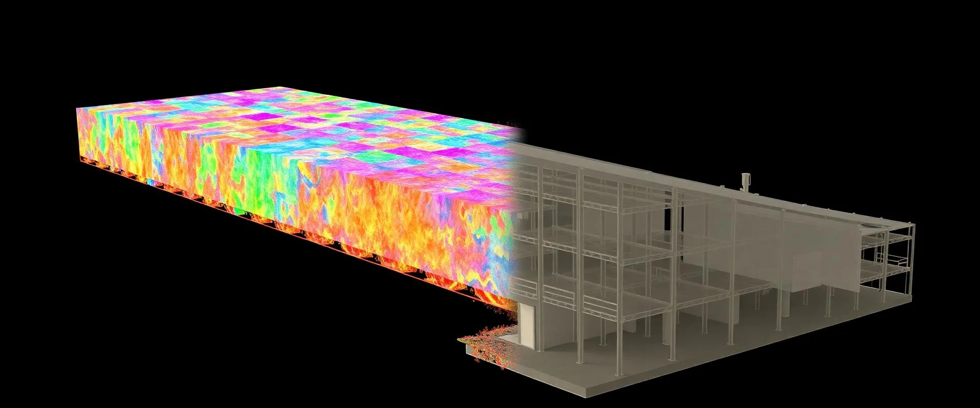
Pick LOD by decision, not ambition: LOD 200 (±20–30 mm, 3–6 days per 100k sq ft) for feasibility, LOD 300 (±10–15 mm, 10–15 days) as the default for design and coordination, and LOD 400 only for the 5–15% of a building where fabrication depends on it. A targeted split on a 92,000 sq ft Columbus conversion saved 9 business days and $65,000 in avoided change orders.
When someone asks for a “full LOD 400 model,” my first question is always: where do you truly need fabrication-level detail, and where will a clean, reliable background do the job? The right answer usually saves weeks and tens of thousands of dollars. Here’s a practical, field-tested way to choose the right LOD from a 3D scan, without overmodeling your project.
What does LOD actually control in a Scan to BIM workflow?
LOD (Level of Development) isn’t about how fancy the model looks. It defines:
- The element geometry you’ll receive (schematic mass vs. exact faces and edges)
- The tolerance you can rely on for dimensions and coordination
- The attributes included (system names, materials, IDs)
- The intended use (planning, CDs, coordination, or fabrication)
On scan projects, LOD lives and dies on three inputs:
1) the quality of the point cloud,
2) the clarity of the modeling scope, and
3) the tolerances you write into the spec.
We capture interiors with the NavVis VLX3 (mobile SLAM) and supplement with Leica RTC360 or Faro Focus when long-range line-of-sight or exterior tie-ins demand it. With surveyed control targets and cloud-to-cloud registration, we hold ±6–8 mm registered accuracy building-wide, with point spacing of ~5–10 mm at 10 m. Typical E57s for a 100,000 sq ft building land between 60–100 GB, depending on decimation.
“If you think you need LOD 400 for the whole building, you probably don’t. Target it to the areas where steel, duct, or millwork will be fabricated. Everywhere else, LOD 300 (or even 200) is faster, lighter, and just as effective.”
Quick Comparison: LOD 200 vs 300 vs 400 from Scans
| Item | LOD 200 | LOD 300 | LOD 400 |
|---|---|---|---|
| Primary use | Planning, test fits, early cost models | CDs, coordination, clash detection | Fabrication and install in targeted zones |
| Geometry | Schematic masses/centrelines; approximate sizes | Modeled to faces/edges as-built | Modeled to fabrication detail where visible |
| Typical tolerance (from scan) | ±20–30 mm global | ±10–15 mm global | ±6–10 mm local (targeted) |
| Systems typically included | Arch/structural primary, major MEP trunks as centrelines | Full arch/structural, main MEP routed to faces, key penetrations | Detailed MEP in scope areas, hangers/inserts where visible, custom millwork |
| Modeling effort per 100k sq ft | 3–6 business days | 10–15 business days | Highly variable; 2–4 days per complex room or riser bank |
| Files and performance | Light; easy to share | Balanced; workable on most machines | Heavy; split by area to manage performance |
| Typical deliverables | Revit model + levels/grids; 2D plans if requested | Revit + sheets for plans/sections; clash-ready | Revit with fabrication-ready elements; detailed 2D for shop interface |
Note: Many teams also use “LOD 350” for clearances/interfaces; in practice, our LOD 300 scopes usually include 350-level openings, sleeves, and datum where it prevents coordination misses.
Where does each LOD fit best?
LOD 200: Fast answers, early decisions
- Best for: feasibility, adaptive reuse test fits, precon takeoffs, high-level phasing.
- What you get: walls, floors, roofs, columns, and major MEP trunks as generalized geometry aligned to reality; levels and grids you can trust; typical rooms blocked out within ±20–30 mm.
- Why teams like it: lower cost, smaller files, and fast turnaround. On a 120,000 sq ft office in Columbus, we scanned in 1.5 days, registered in 3 days, and delivered LOD 200 in 6 business days. The GC’s estimator used it for early pricing within the week, avoiding guesswork on slab steps and deck heights.
Related reading: Accurate As-Built Floor Plans for Renovation Projects and Scan to CAD: Converting Point Clouds into Accurate 2D Drawings. If you only need plans and elevations, consider our Scan to CAD or Floor Plans packages.
LOD 300: The safe default for CDs and coordination
- Best for: background conditions in Revit, dimensioning to as-built faces, locating penetrations, clash detection with new work.
- What you get: walls to centerlines and faces, beams with camber shown if captured, slab edges and slopes, openings, parapets, mechanical rooms modeled to faces, primary piping/duct routed to actual paths with major valves and dampers when visible.
- Why teams like it: dependable dimensions to the object itself. Expect ±10–15 mm building-wide in the model, with local features inside ±6–10 mm depending on sightlines and control.
Pair LOD 300 modeling with the right spec. Start here: How to Write a 3D Scan Deliverable Spec That Protects Your Project and our Scope of Work Template for Scan to BIM Projects. We build these models from E57/RCP/LAS point clouds captured and indexed per your coordinates; see Point Cloud File Formats Explained: E57, RCP, LAS, and PTS.
LOD 400: Only where fabrication depends on it
- Best for: mechanical rooms with tight new equipment, pipe racks where prefabrication is planned, stair/millwork packages, specialty steel tie-ins.
- What you get: detailed geometry for installation—precise offsets, flange locations where visible, verified hanger positions if captured, and tight local tolerances supported by supplemental terrestrial scans or additional passes. We model what the scan can actually see; we won’t invent data behind insulation or obstructions.
- Why teams like it: it de-risks prefabrication. We typically constrain LOD 400 to 5–15% of a building: the rooms or runs that justify the effort.
For insight on throughput and field methods, see Inside the NavVis VLX3: How Mobile LiDAR Captures Buildings at Walking Pace and our core Scan to BIM service page.
Field Notes from Ohio: Targeted LOD Saves Real Money
Columbus, Brewery District. A 1920s warehouse headed for office conversion: 92,000 sq ft over four levels. The architect initially asked for “LOD 400 everywhere to be safe.” We suggested a split:
- LOD 300 for shells, structure, shafts, and egress paths
- LOD 200 for long, untouched storage wings
- LOD 400 only in the future café/kitchen and a main stair rebuild
Scope and performance:
- Capture: 1.5 field days with the NavVis VLX3 (two operators). We tied to control using surveyed checkerboards on each level and a vertical transfer. Supplemental RTC360 sets handled courtyard facades.
- Registration/QC: 3 days. We used cloud-to-cloud with target constraints, ran M3C2 distance checks in CloudCompare, and spot-verified 20 dimensions with a steel tape and Disto.
- Deliverables: E57 + RCP, a Revit model with LOD 300/200 as defined, and LOD 400 for two rooms (kitchen + stair). Turnaround: 12 business days from mobilization.
Outcomes:
- The team shaved ~9 business days off the schedule compared to full LOD 300/400 everywhere.
- File weight stayed manageable (RVT at 480 MB versus a projected 1.2 GB).
- The GC documented $65,000 avoided in change orders tied to stair headroom and slab transitions discovered early—plus 14 fewer RFIs during DD.
This is typical. We see 15–30% modeling savings when LOD is matched to actual design and fabrication needs.
What Accuracy and Density Do You Actually Need?
Capturing a building is only half the story; controlling error is the rest.
- Capture platform: NavVis VLX3 (mobile LiDAR, SLAM) for interiors at walking pace; RTC360/Faro Focus for exterior tie-ins and long corridors with limited features.
- Control and registration: We deploy survey control in larger facilities and on multi-level projects. Registration uses target constraints plus cloud-to-cloud to maintain global integrity. Expect ±6–8 mm registered accuracy to control across typical floor plates, with feature density of ~5–10 mm at 10 m.
- Deliverables: E57 master, indexed RCP for Autodesk Recap, LAS on request; coordinated As-Built Documentation packages available. We build Revit at the agreed LOD and can also deliver 2D plans/sections if that’s all you need.
If you’re coordinating new steel or equipment, demand the tolerance in writing. If your team only needs square footage and corridor widths, don’t pay for more.
Preservation and Historic Work: Scan as a Support Tool
For preservation, 3D scanning is a strong companion to traditional documentation—not a replacement. On courthouse and church projects around Mansfield and Cleveland, we:
- Scan for global geometry, alignments, and settlement checks.
- Hand-measure profiles and moldings, trace unique details from high-res photos, and verify key historic dimensions on site.
- Produce measured drawings and models that honor both the captured reality and the craft.
If you’re planning HABS/HAER-quality records, we combine scanning with conventional methods to meet archival standards. See our work with preservation teams.
How do you write a spec that prevents overmodeling?
A tight spec beats assumptions. Put this in your RFP or SOW:
- LOD by element and area: “LOD 300 for architectural shell and primary structure; LOD 200 for storage wing; LOD 400 for Mechanical Room 1 and Stair A.”
- Tolerances: Declare global and local tolerances (e.g., “±10 mm local for Stair A geometry”).
- Levels, grids, coordinates: Define the project base point and survey point. Share any existing control.
- Deliverables and formats: “RVT 2023, one combined model + linked per-floor files for LOD 400 areas; E57 master cloud; RCP indexed set for Recap.”
- QC: Require a short QC report with registration stats, sample deviation heat maps, and five tape-check photos.
Use these as a starting point:
- How to Write a 3D Scan Deliverable Spec That Protects Your Project
- Scope of Work Template for Scan to BIM Projects
What timelines and costs should you expect?
These are ballpark numbers for planning. Actuals vary by complexity, clutter, access, and coordination with active operations.
- Capture speed: 60,000–120,000 sq ft/day with NavVis VLX3 in typical office/industrial interiors at walking pace; slower in dense mechanicals.
- Registration/QC: 2–5 business days per building, depending on levels and control.
- Modeling from point cloud:
- LOD 200: ~3–6 business days per 100,000 sq ft
- LOD 300: ~10–15 business days per 100,000 sq ft
- LOD 400 (targeted): plan 2–4 days per complex room, riser, or staircase
Cost impact of right-sizing LOD is real. On 150,000 sq ft office retrofits, switching full-LOD requests to a mixed LOD plan typically returns $20,000–$45,000 in modeling savings and chops 1–2 weeks off precon. It also keeps the Revit file usable for everyone.
How do we package deliverables?
- Point cloud: E57 master (60–100 GB per 100k sq ft typical), RCP/RCS for Autodesk, LAS if needed for analysis.
- Revit: Version per your standard, with levels, grids, and shared coordinates set. LOD clearly tagged by scope areas. We can issue separate links for LOD 400 zones to keep performance clean.
- Extras on request: 2D sheets from the model, floor plans/elevations, or Scan to CAD deliverables for trades who don’t live in Revit. See Building 3D Laser Scanning for a full service list.
Bottom Line
Pick LOD to match decisions, not ambition. Use LOD 200 for feasibility and speed. Default to LOD 300 for CDs and coordination. Reserve LOD 400 for the few rooms or runs where fabrication relies on millimeter truth. That mix gives you accuracy where it counts and keeps both the schedule and the model under control.
If you’re unsure where the line should fall, we’ll review your scope and mark up a floor plan with recommended LOD zones—no charge. We’ve done this on hospitals in Cleveland, warehouses in Mansfield, and downtown rehabs in Columbus and Cincinnati. It’s a quick exercise that pays for itself on day one.