TL;DR
Scanning supports preservation documentation — it does not replace it. The point cloud supplies measurable geometry for SHPO submissions, Section 106, HABS/HAER support, and tax credit applications (orthophotos at 1/8" = 1'-0", ±6 mm registered), while measured drawings, photographs, and archival research remain the conservator's craft.
Documentation That Preserves What Matters
Preservation decisions hinge on evidence. Measured evidence. Photographic evidence. Context. Our role is to help you build that record without touching the fabric you’re trying to protect. We use 3D laser scanning as a support tool alongside field notes, photographs, archival research, and drawings — not instead of them. When done right, you get reliable geometry, measurable imagery, and a defensible baseline that stands up to SHPO reviews, Section 106, and tax credit audits.
We typically deploy a NavVis VLX3 for fast interior capture and a Leica RTC360 or FARO Focus for tight ornamental work and exterior tie-ins. On most projects we register to survey control and deliver a point cloud at ±6 mm overall registration accuracy with point spacing of 5–10 mm at 10 m. That density is enough to read settlement, trace molding profiles, and generate clean elevations.
Where does scanning fit in a preservation workflow?
- Condition assessments: dimensional baselines, measurable panoramas, and deformation checks that inform the consultant’s report
- SHPO submissions: plan/elevation sections grounded in real measurements, not estimates
- HABS/HAER support: orthographic control for large-format drawings and photo sets
- Tax credit documentation: before/after conditions, square footage verification, and character-defining feature mapping
- Section 106: effects analysis and archival capture when mitigation is required
See our tools and specs overview on the Technology page, or browse similar work in the Portfolio.
Condition Assessments With Measurable Context
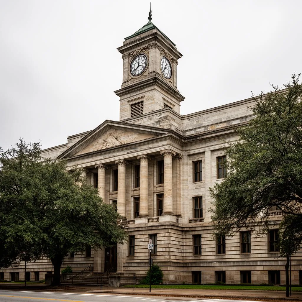
On condition surveys, we combine walking-pace SLAM with static setups where detail demands it.
- Typical interior pass with NavVis VLX3: 30,000–50,000 sq ft per day, panoramic images every 2–3 m
- Static detail scans for ornament or tight spaces: 3–5 min per setup with the RTC360, 2–3 mm spacing at 5 m
- Registration: cloud-to-cloud plus target/total station control; coordinate frames aligned to your survey or project grid
- Output: E57 master (80–150 GB for a mid-size building), RCP for Autodesk Recap/AutoCAD, and colorized LAS for archival storage
What you can read from that data:
- Plumb and flatness across walls and floors (±6 mm registered accuracy)
- Differential settlement and deflection across spans
- Surface conditions via 134 MP-class panoramas with measurable pixels
In Columbus last winter, we documented a 1908 firehouse before adaptive reuse. Two field days (46,000 sq ft), 1,420 panoramas, 96 GB of E57 data. The architect flagged a sagging timber roof bay in the scan — 1.1 inches of deflection across 28 feet — later confirmed on site. That note steered the engineer’s probe openings and cut a week of guesswork.
SHPO Submissions: Clear, Measurable Drawings
Whether you’re preparing a Part 2 or coordinating a window replacement package, measured drawings make review faster. From the point cloud we produce:
- Floor plans and elevations via Scan to CAD or Floor Plans, issued as DWG and layered PDFs
- Orthophotos for façades and interiors (1/8" = 1'-0" or finer)
- Context sections showing relationships between new work and historic fabric
- Annotated panorama sets keyed to drawing callouts
Typical turnaround for a 50,000 sq ft building:
- Draft plans/elevations: 7–10 business days
- Final sheets with notes and dimensions: 12–15 business days
We don’t tell you what’s “contributing” or “character-defining.” You do. We provide the geometry and imagery that make those calls defensible and easy to explain to reviewers.
If you’re setting model expectations, see our guide on LOD 200 vs 300 vs 400 and our Scan to BIM service for Revit deliverables.
HABS/HAER-Level Support (Data In, Craft Out)
HABS/HAER documentation is a craft. Scanning gives you the dimensional scaffold:
- Dense point clouds for plan/elevation control lines, profiles, and true arcs
- High-resolution, colorized data to backstop large-format inked drawings
- Orthographic exports and line extraction to speed drafting while respecting required line weights and conventions
For fragile details (plaster cornices, carved capitals), we use tighter static passes. Expect 2–3 mm spacing at 5 m, sufficient for profile tracing. Where the standard calls for photography, we supplement the pano set with bracketed DSLR images.
Teams still create compliant sheets; scanning just cuts the re-measure loop. If you’re scoping a HABS package, our post on how to write a scan deliverable spec can help set expectations.
Tax Credit Applications: Clean Baselines and Fewer Surprises
Federal and state historic tax credits reward clean documentation. Scanning supports:
- Verified building area for pro formas (we provide gross and rentable area takeoffs)
- Before-condition records that match Part 2 scopes and Part 3 certifications
- Feature inventories: windows, storefronts, stair details, pressed tin ceilings — all photo-referenced and measurable
On our Downtown Mansfield case study, we captured 180,000 sq ft across multiple buildings in three weeks to support a large adaptive reuse package. The team cut RFI volume by 30% during design because the model and drawings agreed with reality from day one.
Section 106: Effects Analysis and Mitigation
If your project triggers Section 106, measured data keeps the conversation factual.
- Document existing conditions within the Area of Potential Effects (APE) before any work
- Quantify visibility and adjacency: sections, sightlines, and massing overlays from scan-based models
- Archive a full spatial record (E57/LAS, orthophotos, PDFs) as mitigation when adverse effects are unavoidable
We often deliver a “pre” capture and a smaller “post” capture to confirm treatments — useful for MOA commitments and agency files.
How do you choose capture methods for historic work?
Different spaces call for different tools. Here’s how we typically decide.
| Situation | NavVis VLX3 (Mobile SLAM) | Terrestrial (RTC360/FARO) |
|---|---|---|
| Large interiors, repetitive bays | Fast (30–50k sq ft/day), sufficient for ±6 mm registered | Slower; used only at key tie points |
| Ornamental details, small rooms | Supplement with static for 2–3 mm spacing | Primary tool for profiles and tight geometry |
| Exterior façades, tall elevations | VLX3 for context; static for vertical accuracy | Primary for elevation orthos and control |
| Courtyards/alleys with poor GNSS | Works; relies on loop closure and targets | Works; better for long, linear exteriors |
| Deliverables: plans/elevations | Excellent baseline | Excellent, with crisper edges for linework |
We often hybridize: mobile for coverage, static where the drawing team needs razor-sharp edges.
What do we deliver — and how?
- Point clouds: E57 master, plus RCP for Autodesk users and LAS for archives; see our primer on point cloud file formats
- Panoramic imagery: colorized, measurable, geo-linked to the cloud
- CAD sheets: DWG/PDF plans, elevations, and sections via Scan to CAD
- Revit models: LOD 200 or 300 via Scan to BIM, aligned to your templates
- Orthophotos: façade/interior wall orthos at project scale
- QA report: registration stats (target residuals, loop closures), control lists, and coordinate metadata
Accuracy and control:
- Registration: cloud-to-cloud with targets; survey control tied to site benchmarks
- Typical results: ±6 mm registered within a floor plate; tighter in localized static sets
- File sizes: 60–150 GB for mid-size buildings; we segment by level/wing to keep RCPs manageable
Field Notes From Ohio: A Church in Cleveland, A Courthouse in Mansfield
In Cleveland’s Tremont neighborhood, we scanned a 1890s brick church ahead of repointing and interior stabilization. 62,000 sq ft across sanctuary, transepts, and basement. Two field days:
- VLX3 interior loops for coverage; 18 static setups for clerestory windows and ribbed vaults
- 2,060 panoramas; 112 GB E57
- Elevation orthos at 1/8" = 1'-0" revealed a 1.6° out-of-plumb west wall — not obvious to the eye, vital for scaffold planning
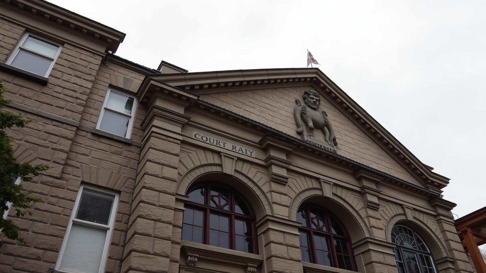
Closer to home in Mansfield, we documented a courthouse annex before HVAC replacement. Old plaster, ornate grilles, tight mezzanines. We paired mobile capture with 9 faucet-tight static scans to trace a crown profile the millwork shop needed. Turnaround was 12 business days for CAD elevations and a LOD 200 model. The GC skipped 14 extra site walks and estimated a $24,000 soft-cost savings from reduced rework and travel.
Preservation First, Technology Second
We don’t determine significance. We don’t write your narrative. We stand behind the tape and create a measurable baseline that respects the building and speeds your work. Scanning supports — it does not replace — the skills of preservation architects, historians, and conservators. Our As-Built Documentation process is built around that principle.
Practical Prep: Make the Most of a Scan Day
A little coordination goes a long way. For owners and design teams, here’s what helps:
- Access: keys for all rooms, attics, and towers; ladder/boom plans for inaccessible balconies
- Lighting: keep fixtures on; bring temporary lights for windowless spaces
- Staging: remove movable obstructions where safe; label rooms to match existing drawings
- Protection: we use non-invasive targets and respect no-touch areas; flag fragile finishes in advance
More tips in our site guide: How to Prepare Your Site for a 3D Laser Scan.
When do you need us?
- Early: to anchor a condition assessment before scope and budgets harden
- Mid-design: to verify hidden geometry and reduce RFIs
- Pre-construction: to set a baseline before demolition or abatement
- Closeout: to document treatments for Part 3 and archival files
If you’re deciding between drawings only or adding a model, our Building 3D Laser Scanning overview explains typical preservation deliverables and costs.