TL;DR
We captured this 96,400 sq ft 1920s warehouse in 2.5 field days at ±6 mm registered accuracy and delivered an LOD 300 Revit model 18 business days later. The GC cut contingency by $85,000, 17 RFIs were avoided during design, and MEP coordination started three weeks early.
A century ago, a brick warehouse off North Main in Mansfield took in freight on one side and sent out finished goods on the other. Timber posts, mushroom capitals, steel beams the size of Buicks. The bones were good. The plan now: 72 market‑rate lofts and ground‑floor retail without sanding off the character that made the building worth saving.
We were brought in to document the existing conditions before design started. Not to replace the architect’s field work or the preservation team’s hands-on assessments, but to give everyone a precise digital backdrop so decisions could be made once, not three times. Here’s how we captured it, what we delivered, and what the team learned along the way.
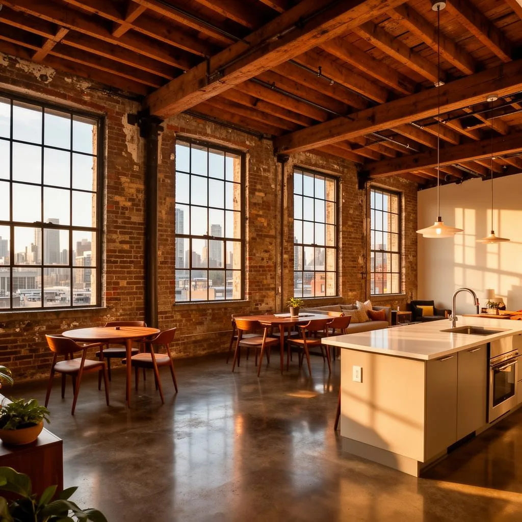
Project at a glance
- Building: 96,400 sq ft, basement + 4 floors, two stair towers, one disused elevator shaft, timber-and-steel hybrid frame, solid brick exterior
- Capture window: 2.5 field days in February (interior first, exterior on a clear morning)
- Tools: NavVis VLX3 (SLAM, mobile), Leica RTC360 (terrestrial) for stair cores and MEP chases
- Control: 36 surveyed control points; black/white targets and mini-prisms tied to a floor datum and project north
- Accuracy (registered): ±6 mm across floors (RMS 4.8 mm within spaces; 6.3 mm across vertical cores)
- Point density: ~5–8 mm spacing at 10 m in open floors; ~3–5 mm in static cores
- Data volume: 280 GB raw mobile SLAM; 42 GB RTC360 raw; 92 GB filtered E57 master; 110 GB indexed RCP/RCS for Autodesk Recap
- Deliverables: E57/RCP/LAS point clouds, LOD 300 Revit model, 2D AutoCAD floor plans and elevations
- Turnaround: Point cloud in 7 business days; LOD 300 model in 18 business days; 2D sheets in 10 business days
- Measurable impact: GC cut contingency by $85,000; 17 RFIs avoided during schematic/DD; no return site visits for dimensional checks
Field workflow in Mansfield
Day 1: Establish control, find the loops
We started with control. A two‑person crew set 36 control points with a total station — one per ~2,500 sq ft, tighter around cores and along the exterior wall where bowing was suspected. We aligned to the architect’s assumed project north and level datum so the model would drop into Revit without gymnastics.
With control set, we walked the VLX3 in long, overlapping loops: basement to first floor, then back to the baseline to close. Loop closures keep SLAM honest. We used paper targets to mark tricky transitions at stair openings and the elevator shaft so registration had hard ties.
“When your loop closures hit under six millimeters across four floors, you feel it in your shoulders — the building ‘clicks’ in,” our field lead said over coffee at relax, it’s just coffee on Main.
Day 2: Cores and character details
The RTC360 came out for the vertical cores, the old freight elevator, and a tangle of legacy piping we knew the MEP designer would ask about. Static scans give cleaner geometry where steel and brick meet at tight angles. We ran 47 setups, 2–4 minutes each, with HDR imagery where daylight reached. The VLX3 handled the open floor plates and long corridors at walking pace.
A note from the field: the second-floor slab had a 1.9-inch crown across 90 feet; we caught it in the heat maps and tagged it for the structural engineer. Also, pigeon debris in the elevator pit is not SLAM-friendly. We tarp-covered and scanned from the threshold, then filled the gap with targeted terrestrial shots.
Exterior pass
We caught exteriors in a three-hour window the next morning. No power on site, so we brought portable LEDs for shadowed recesses. The brick’s stretcher/bond pattern read cleanly at ~6 mm spacing from 8–12 m. We avoided freezing rain by 24 hours — a small miracle in Richland County in February.
Why did the mix of mobile and static scanning work?
Mobile SLAM let us move fast across big floor plates. Terrestrial scans nailed the details where small errors multiply — stairs, shafts, and MEP tie-ins. The combination gave the design team confidence across scales, from massing to millwork.
| Approach | Best for | Typical field time on this project | Point density / accuracy | Outcome |
|---|---|---|---|---|
| NavVis VLX3 (mobile SLAM) | Open floor plates, long corridors, exterior facades | 11 hours | 5–8 mm at 10 m; ±6–8 mm registered | Clean global geometry, consistent levels, fast coverage |
| Leica RTC360 (terrestrial) | Stairs, elevator shaft, tight MEP clusters | 3.5 hours (47 setups) | 3–5 mm at 10 m; ±3–4 mm local | Crisp edges, better planar fits, fewer registration artifacts |
Both datasets were registered together using cloud‑to‑cloud with target constraints. We kept loop closure residuals under 6 mm and floor‑to‑floor drift under 4 mm by anchoring each level to control and checking live against the previous day’s bundle.
Which deliverables did the team actually use?
- Point cloud master in E57 with individual level/class layers; RCP/RCS sets for Autodesk Recap. If you’re choosing formats, this primer helps: Point cloud file formats explained.
- Revit model at LOD 300: structural grids, columns, beams (with actual flange depths where visible), floor slabs with slopes, exterior and interior brick walls with variable thickness, window and door openings, stair geometry, and shaft framing. We coordinated the model spec early — the same way we recommend in our guide on writing a 3D scan deliverable spec.
- AutoCAD plans and exterior elevations for early pricing, built from the point cloud and model with clear lineweights and dimensions. If 2D is your immediate need, see our Scan to CAD and Floor Plans services.
- QA pack: control report, registration stats, heat maps for slab variance, and a short video walkthrough from Recap showing line‑of‑sight checks around cores.
Designers pulled sections anywhere. The preservation consultant overlaid brick wythe thickness against deterioration maps. The GC used clearances around the stair enclosures to pre‑select rated assemblies that would fit without furring into the corridor. That prevented a late shuffle that usually costs weekends.
Preservation needs a complete picture — scanners don’t tell the whole story
We scanned, but we also measured by hand where scanning can mislead. For example, multi‑wythe walls read as a single mass in a point cloud; coring and borescope checks confirmed three wythes with variable lime mortar in two test bays. For historic trim, we photographed and field‑sketched profiles that would never justify modeling at LOD 400. Preservation is built on corroboration.
3D capture supported the preservation work; it didn’t replace it. That balance is our standard on warehouses, theaters, and mills. If you work in this space, start here: Adaptive reuse and Historic preservation.
What results could the owner count?
- 17 RFIs avoided in DD. The usual suspects: stair headroom, elevator overrun, beam pocket depths, and a quirky brick pilaster that pinched a unit entry.
- Contingency reduced by $85,000 after the GC priced using verified slab slopes and actual beam locations. Less fear, fewer allowances.
- MEP coordination started three weeks earlier because the LOD 300 model and RCP were issued 7 days after capture. No one waited for a 400-level model to make decisions.
- Field revisits: zero. The architect’s team checked centroids and clear heights in the cloud from their office in Columbus, same day. That’s the benefit of accurate As‑Built Documentation from the outset.
If you’re curious how this compares to another local effort, our related case study shows a larger scope downtown: Downtown Mansfield: 180K Sq Ft in 3 Weeks.
How should you plan your next warehouse conversion scan?
- Define tolerances in writing. For this project: ±6 mm registered overall, ±3–4 mm in cores. Put it in the scope and the model spec. Here’s a template to get you started: How to write a 3D scan deliverable spec.
- Pick LOD by decision, not by habit. LOD 300 gave the team what they needed to set units, shafts, and risers. Save LOD 400 for fabrication—only where it pays off.
- Allow time for registration and QC. We allocated two days after field work to clean, classify, and check loop closures. That time made the model better and the DD phase faster.
- Don’t skip control. On multi‑level buildings, control and loop closures keep floors aligned. Targets at stair heads and shafts are cheap insurance.
- Prep the site. Clear access to cores, remove loose debris where possible, and coordinate with building access. A quick read helps: How to prepare your site for a 3D laser scan.
- Share once, use everywhere. Host the RCP on a shared drive the GC can hit; export E57 for consultants who prefer CloudCompare or Cyclone. We tailor packages in our Building 3D Laser Scanning and Scan to BIM workflows so teams aren’t wrestling file conversions.
Tools and specs that matter
- NavVis VLX3 for speed in large interiors; SLAM tuned for long loops with frequent target hits
- Leica RTC360 for stair runs, pits, and the elevator shaft; HDR imagery for context
- Registration: hybrid cloud‑to‑cloud with target constraints; residuals under 6 mm; floors tied to control to lock drift
- Deliverables: E57 master (92 GB), RCP/RCS (110 GB), LAS subsets for civil/landscape, Revit model (LOD 300, 280 MB), 2D DWGs
- Software: Autodesk Recap for indexing, Revit for modeling, AutoCAD for sheets; occasional CloudCompare for variance analysis
- Handover: one-page read‑me with coordinate system, units, level names, and view templates for plug‑and‑play use in Revit
The bottom line
The 1920s warehouse kept its timber, its steel, and its story. The design team got the truth on day one. Scanning didn’t replace judgment — it amplified it. That’s how you keep character, control cost, and move faster without guessing.
If your project looks anything like this — brick, timber, steel, uncertain drawings — we can help you set the stage. Browse our technology stack, see similar work in the portfolio, or talk to us about scope.